Track Building
Track Building
First things first. 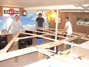 The best source for detailed information regarding the home construction of a conventional routed slot car track is available on Luf Linkert’s site for builders of wood tracks. Although the basic cutting framing and routing of an AC2Car track and a conventional track are similar, note that there are differences in the AC2Car system of track design that will be outlined below.
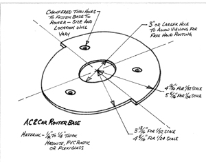
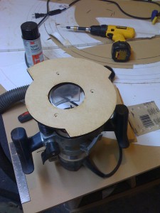
The Old Slot Racer how-to page, and an informative DVD that Luf offers on that site, will help you through the basic steps of layout, routing, and supporting a track made of Medium Density Fiberboard (MDF). This 1/2″ thick MDF comes in 4’X8′ or 4’X10′ sheets that are fairly inexpensive and readily available at local home building supply outlets. The best thing about MDF is that it’s so smooth, making it ideal to paint without the priming and sanding that is required on wood particle board. And it’s flexible, which lends itself to the twisting required when banking and changing elevations. Note that in Luf’s video, and other past how-to magazine articles, the instructions are directed toward building a typically wide, pass anywhere, style of slot car track. Conventional tracks like this are very wide and take up gobs of floor space. By designing and building an AC2car style track, you will be creating a narrower and longer track. Using our AC2Car system of track design, you can build a track with the same tools and the same technique, but with double the racing and double the cars in the same space. This is done by following the pattern for laying out slots for AC2Car tracks shown in Drawing #1. As outlined on the above sight, a 1/8″ flexible PVC strip gets pressed into the first routed slot, and is used as a guide for the special cammed router base to easily cut the remaining slots. Drawings to make your own AC2Car cammed router base, used to make these uniquely spaced slots based on the AC2Car pattern, can be seen below in Drawing #2. Also, a how-to section showing Dave actually routing slots will be coming later too.
Design: Computer Aided vs. Graph Paper
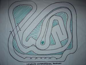
Dave’s track was never planned on more than (4) 8 1/2″ X 11″ pieces of graph paper taped together.
We laid out and built the outer perimeter of the track in the space allowed, then designed the inner turns to fit the space as tight as possible. This way we physically got the most linear feet of track into the space. The 2 years of computer aided design put into Northline Raceway, might have been better used creating sawdust. But of course, we were inventing an unprecedented blocking and passing scheme, so it was necessary at the time. Now that we know the optimum AC2Car slot pattern to make it work, an AC2Car track need not be put on CAD unless you actually like doing that. You will find that if you design it on the tube, then cut it out full scale to match the drawing, there will be tons of changes to get it to fit right. This is because after flexing the track sections to bank the turns the lengths and shape of track sections will change. Plus, the rising and falling of track levels will foreshorten stretches of track too. The final exact shape and size can’t be easily replicated in CAD. So, laying out individual stretches of track on wood and fitting it right where it will finally go, is the most efficient way to maximize the track length in a given space. Designing, fitting, routing slots and finally mounting the pieces, one stretch of roadway at a time, worked out best for us.
Slot Spacing, 4 cars
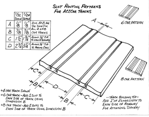
When making an AC2car style track, you no longer need to make wide, out of scale roadways. As we outlined on the detailed information page,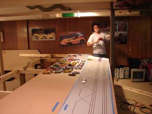 an AC2Car track is usually half the width of a commercial style track. Again, this equates to almost double the length of racing in the same amount of your valuable floor space. Given that with AC2Car electronics two cars share each lane with independent control, a lane change area is required, and a unique pattern of slots must be cut all the way around the track. This pattern allows passing, yet narrows the track giving you the ability to design a much longer layout. Note that all measurements recommended here, are for 1/32 scale unless otherwise specified. They have been tried and tested on Northline Raceway. All dimensions are measured from slot edge to slot edge, or slot edge to track edge. Not from the center line of the slots. (see Drawing #1) A conventional 4 car track, having the typical 4 slots cut 3 1/4″ or 3 1/2″ apart would be 14″ to 16″ wide. In comparison, an AC2Car track designed to run the same (4) 1/32 scale cars requires two groups of parallel slots cut 7/8″ apart separated by a 2 3/4″ space between the two groups of slots. This is the minimum width needed for 1/32 scale cars to pass. The outer and inner most slots on either side, are located 1 1/2″ in from each side of the roadway. With the 4 routed slots being 1/8″ wide each, an AC2Car home routed track for (4) 1/32 cars, would add up to be only 8″ wide!
The Simple Math
Again, in 1/32 scale a minimum dimension of 1.5″ allows 1/4″ clearance to each edge of the track, and a space of 2 3/4″ is necessary for cars to pass each other by 1/4″ in the middle. The dimension of 7/8″ is the measurement between the slots grouped to allow 1/4″ copper tape to be used. 1.5″ clearance to outside of track + 1/8″ slot cut for cars A and B to share on the outside of roadway + 7/8″ gap between slots + 1/8″ slot cut for cars C and D also to run on the outside of roadway + 2 3/4″ for cars to pass + 1/8″ slot cut for cars A and B on the inside of roadway + 7/8″ gap between slots + 1/8″ slot cut for cars C and D on the inside of roadway + 1 .5″ clearance to inside track edge = 8″. So on a 4 car 1/32 AC2Car track a total width of 8 ” is all that’s required on straight sections.
click here to download a pdf of Drawing #1
Slot Spacing, 6 to 8 cars
AC2Car tracks designed to run 6 cars have two groups of 3 slots in each group. That’s 6 cars racing on a track only 9 3/4″ wide. And, tracks running 8 cars have two groups of 4 slots on either side of the road. That’s 8 cars racing on a track that is only 11 1/2″ wide. (Conventional 8 car wood tracks are over 28 inches wide!) In all cases 1/32 scale AC2Car designed tracks are separated by a 2 3/4″ space between the groups of slots. 1 1/2″ to the edges and 7/8″ between slots in each group.
Larger Scale Racing
To design AC2Car tracks for 1/24 scale cars, the space between each slot in the group remains 7/8″. But, the separation between each group of slots should be 3 1/4″. The distance from the outer slot edges to the road edges is 1 3/4″ minimum. At the turns, the longer 1/24 scale cars need about 3 1/2″ from the outer slot to the track edge, or wall, to allow for total clearance when fishtailing on the outside.
Designing turns
The slot patterns in Drawing #1 for cars in 1/32 and 1/24 scale, show the minimum requirements needed to negotiate the straight sections of AC2Car routed tracks. They have been proven out on my Northline track. In fact, the 2 3/4″ dimension to allow cars to pass is better at turns than the typical 3 1/4″ to 3 1/2″ because, although cars can lean on each other, they tend not to be able to get a pendulum swing and bang hard to nerf outside cars off. The minimum dimensions of slot patterns above, give builders max use of their space to design the largest layout possible. However, at each turn the track must be made wider. Real race tracks widen at turns, and yours should too. The distance from the outside slot to a wall or guard rail affects whether a car can lean on it to increase speed. The tighter the turn, the more the leaning outer car benefits. A definite increase in speed for the outside slot occurs if the distance to a wall is 2.5″ or less. With 3″ a driver can touch the wall, but the attitude of the car is such that speed is scrubbed off. At 2.75″ a car can lean on a wall and it’s a wash, speed wise. All this is to say, do not design a layout with less than 2 3/4″ to 3″ of skid apron on the outside of the turn. So, in 1/32 scale, for a flat unbanked turn, we have found that a 3″ spacing from the outside slot to a wall, or guard rail, gives total clearance.
Banking
Cars fishtailing way out on a 3″skid apron looks cool, but not only is it unrealistic, it’s far slower. Space eating skid aprons can be minimized, and far less shunts occur, when turns on your layout are banked a bit. Bank every turn for the sake of space and realism. The 1/2″ MDF is a supple enough building material to allow a previously routed section of track to be banked by screwing down the apex and forcing up the outside with glued wooden shims. These common wood wedges can be bought or made for little price. Just banking the turn measured at it’s peak 1/8″ for every 6″ makes the cars handle better. Tipping it higher to 1/4″ every 6″ makes the turn as banked as prototypical road courses. Finally, 3/8″ of banking every 6″ will make a turn almost fool proof. By using a robust 2X4 framework below the MDF track and using shims, construction glue, and drywall screws, one can torque sections of pre routed track into a grade that pitches up and away from the apex of each turn. It does not take much to create a bit of banking which dramatically adds to traction and realism. The banking is hardly noticed once scenery goes in, but not only does it make racing flow smoother, it really makes the track look like a miniature road course! It’s not hard to do and I highly recommend it.
Apex issues
The inside dimension from slot to track edge on tight radii (<10″ radii) must be enlarged so that a long wheelbase car’s rear inside tire clears the apex at slow speeds. This is especially true for 1/24 scale tracks. Placing a raised apex curb 1 1/2″ from the inside slot will allow rear tires to bump it at slow speeds, desloting the cars. Every slot that turns on less than a 10″ radii should have the inside slot to edge of the track dimension increased to 2″ or 3″ to avoid this problem.
