Racing Action on Jimmy’s Northline Raceway
Racing action from February 16th at Jimmy’s Northline Raceway. 60’s Nascar and Vintage F1 cars.
Racing action from February 16th at Jimmy’s Northline Raceway. 60’s Nascar and Vintage F1 cars.
Some track builders have been asking about the guardrails on the San Marino raod course. Dave used the same method of building a stout yet realistic guardrail when he had to create a robust 1/32 scale rail for the top of his high banked Monza turn on his own scale track. See Legends International Raceway in the “Our Tracks” page and refer to pictures of his Monza turn for more examples. He replicated that effort on Larry’s track below.

This steel Aramco guardrail is actually a silver painted length of 3/4" fluted wood molding available at most lumber yard and building centers.

In this close up you can see the detail that Dave added with a simple lead pencil to imitate fastners at each 3/8" X 3/8" post. The posts are all set 4 1/2" apart with a verticle line representing individual rails 12 feet long. Also note the shading with graphite to weather the guard rail and accentuate the fluting.
Hay bales were used to protect drivers on road courses from the early days of racing up to the early 70’s. Adding hay bales to your road course can give it a remarkably vintage look. Dave added some to Larry’s layout to transform the streets of San Marino into a temporary street racing circuit. You can see more used on Dave’s own track on the “Our tracks” page. His Legends International Raceway replicates the temporary annual racing held at Lemans in the early 70’s.
Thomas wrote in asking…Â Hello Jimmy, I was wondering how did you make those hay bales on your track?
These 2.5″ x 1.25″ x 1″ wired straw bundles are sold under the brand name of Straw Weavers at arts and craft stores like Micheal’s. They are found in the artificial dry flower area. They come in larger sizes but though the smallest is just a bit oversize for 1/32, it’s close enough to add instant detail to the run off areas of any layout requiring that vintage look.
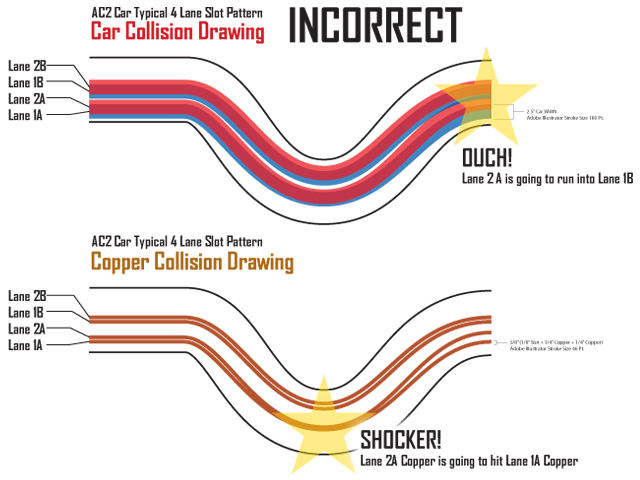
Building on my last post about AC2Car Lane Spacing and Typical Slot Car Spacing and the use of graphic programs such as Adobe Illustrator, here are some visuals regarding what I like to call Car Collision Diagrams and Copper Collision Diagrams. If you recall with AI (Adobe Illustrator) you can draw a singular line and apply visual stroke widths to it. This can enable you to quickly see good and bad areas in your digital track file prep. With a stroke width applied to a line of 180 points (Representing the width of a car) you can create virtual slots and see how cars will mingle with one another. Good and bad can come of this. The most obvious is when you have typical slot car spacing you never want these car lines to run together. With AC2Car its a bit different with the ability to pass. I suggest for a better understanding of the principle slot layout for AC2Car visit our track building page.
Now likewise and more important to AC2Car is taking those same AI lines and applying the stroke value for copper width (Slot and two pieces of copper is a 46 point width) to see where you might have copper from one lane touching an adjacent lane. This is paramount with AC2Car’s tight lane spacing. By going back and forth between car collision stroke width and copper collision stroke width you can succesfully plan your track virtually before routing.
Here is the same section of track, this first image is Correct with NO problem areas with car or copper collisions:

Now this Second Image you can see in the Car Collsion Diagram where Lane 2A is going to hit Lane 1B. Also in the Copper Collision Diagram you can see where lane 2A and 1A Copper would touch one another, ohh ouch shocker!

And there you have it! For Standard AC2Car Spacing, these simple diagrams can help you design your track and once you’re finished you can use the very same files for routing. For the daring you might try squeezes in areas where no cars can pass, or wide open even spaced areas where all lanes can pass integrated into your track. Careful though these types will require more experienced respectable drivers to avoid car on car crashes (From experience on my WLF1 Ring)
Track Builders,
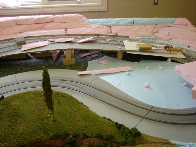
Dave sent us progress pictures of his work on the East side of Larry’s track. I thought this would be a good way to illustrate how Dave uses scraps of foam insulating board as the foundation for scenic burms and hillsides adjacent to the track. Yes, it’s the same technique he uses for rock outcrippings but his final colors, and the texture he glues down on to the foam transforms it into a lusher rolling landscape.
As with all model scenic raceways, the final scenery must be coated with drops of a mixture of 50% water, 50% white glue mixed with a drop of dishwashing soap to help the mixture flow out. Large areas can have this mixture sprayed onto it. This coat of clear setting glue is allowed to dry overnight, then repeated two or three times to achieve the surface hardness necessary. 
This hard scape technique keeps car crash impacts from breaking scenery or scraping scenic material onto the race track.
Rick sent us these great photos of his AC2Car powered track. They highlight some of his latest scenery up dates.
The cool Trans-Am cars in the foreground are resin body scratch built cars (RMS resins)with decals from(Slotcars4u) .
Rick writes, “Big thanks go to Dave Reinecke (RMS resins) and Tim Millward (Slotcars4u) for the super great service”
Note how the roadway on VMO Raceway “undulates”. (I love that word)
A layout routed of MDF gives a track builder the ability to create exciting changes in elevation.
Though Rick’s track is 1/2″ thick, now we are finding that 3/8″ thick MDF makes adding rises, dips and banking even easier.
Great to race on, and even better for realistic track scenery!
Tom from Wisconsin asks “Hi, I was reading a post on Home racing world and happened to notice that on Dave’s track he is using a Lionel 275 watt transformer I am guessing that it is the ZW four train type. Could someone explain how that is wired to the track? Thank you.”
Yes, Dave is using the ZW type. He loves to crank up the voltage!
The terminals are shown here at http://www.davestrains.com/access/ZW250w0109d.jpg/ (This is a Dave unknown to us and was the first picture I found on Google image search)
The terminals on our schematic transformer are labeled 1 and 2. These are equivalent to terminals A and U on the the ZW. So, Dave is not using the full capacity of the transformer. There is plenty of power on a single channel to run 8 standard 1/32 scale motor cars.
On our diagram:
1 = A
2 = U
You can read more about the electrics here:
http://ac2car.org/electrical/
And the track wiring schematic is at the bottom of the page:
http://ac2car.org/blog/wp-content/uploads/2009/03/ac2cartrackwiring.pdf
the car wiring schematic is at the bottom of the page:
http://ac2car.org/blog/wp-content/uploads/2009/03/ac2carcarwiring.pdf
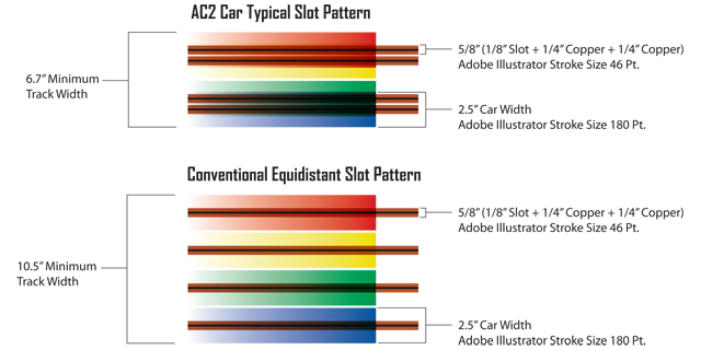
One of the main reasons I was turned on to AC2Car tracks was the lane spacing. This provides two wonderful aspects: Narrower road widths and two unique drive lines around the track for each driver. Narrow road widths mean more track in your space. Two lines around for each driver means twice the fun! Continuing into the future I’ll try and provide some insight into AC2Car track design begining here with this visual:
This is based on a four lane track. You can instantly see the road width advantage of AC2Car Spacing. I use Adobe Illustrator for track design, if you are familiar with it or other graphic vector programs such as Corel Draw you can do it too. I look at a track design in two distinct ways for AC2Car. One is the slot and copper spacing which I call Copper Collision Drawings. Number two is car spacing which I call Car Collision Drawings. In Vector based programs you can draw singular lines and apply stroke widths to them. Stroke widths are merely a visual width of a line, the program and others still see it as a singular no width line which is useful down the road. You can draw line segments with a pen tool in the software and apply the appropriate stroke width to it to see how things are running together. Obviously you don’t want the copper from one lane touching another and depending on the type of track you don’t want cars running into each other. In AC2 Car’s case its a little of both. You can find explanations of that in the Track Building section. In the graphic above I’ve noted Adobe Illustrator stroke values for the copper and slot width as well as a 1/32 scale car width. By combining the two visuals you can create a succesful plan before routing a single piece of wood.