Building on my last post about AC2Car Lane Spacing and Typical Slot Car Spacing and the use of graphic programs such as Adobe Illustrator, here are some visuals regarding what I like to call Car Collision Diagrams and Copper Collision Diagrams. If you recall with AI (Adobe Illustrator) you can draw a singular line and apply visual stroke widths to it. This can enable you to quickly see good and bad areas in your digital track file prep. With a stroke width applied to a line of 180 points (Representing the width of a car) you can create virtual slots and see how cars will mingle with one another. Good and bad can come of this. The most obvious is when you have typical slot car spacing you never want these car lines to run together. With AC2Car its a bit different with the ability to pass. I suggest for a better understanding of the principle slot layout for AC2Car visit our track building page.
Now likewise and more important to AC2Car is taking those same AI lines and applying the stroke value for copper width (Slot and two pieces of copper is a 46 point width) to see where you might have copper from one lane touching an adjacent lane. This is paramount with AC2Car’s tight lane spacing. By going back and forth between car collision stroke width and copper collision stroke width you can succesfully plan your track virtually before routing.
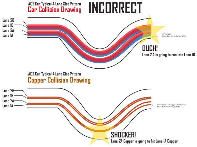
Here is the same section of track, this first image is Correct with NO problem areas with car or copper collisions:

Now this Second Image you can see in the Car Collsion Diagram where Lane 2A is going to hit Lane 1B. Also in the Copper Collision Diagram you can see where lane 2A and 1A Copper would touch one another, ohh ouch shocker!
And there you have it! For Standard AC2Car Spacing, these simple diagrams can help you design your track and once you’re finished you can use the very same files for routing. For the daring you might try squeezes in areas where no cars can pass, or wide open even spaced areas where all lanes can pass integrated into your track. Careful though these types will require more experienced respectable drivers to avoid car on car crashes (From experience on my WLF1 Ring)
Tom from Wisconsin asks “Hi, I was reading a post on Home racing world and happened to notice that on Dave’s track he is using a Lionel 275 watt transformer I am guessing that it is the ZW four train type. Could someone explain how that is wired to the track? Thank you.”
Yes, Dave is using the ZW type. He loves to crank up the voltage!
The terminals are shown here at http://www.davestrains.com/access/ZW250w0109d.jpg/ (This is a Dave unknown to us and was the first picture I found on Google image search)
The terminals on our schematic transformer are labeled 1 and 2. These are equivalent to terminals A and U on the the ZW. So, Dave is not using the full capacity of the transformer. There is plenty of power on a single channel to run 8 standard 1/32 scale motor cars.
On our diagram:
1 = A
2 = U
You can read more about the electrics here:
http://ac2car.org/electrical/
And the track wiring schematic is at the bottom of the page:
http://ac2car.org/blog/wp-content/uploads/2009/03/ac2cartrackwiring.pdf
the car wiring schematic is at the bottom of the page:
http://ac2car.org/blog/wp-content/uploads/2009/03/ac2carcarwiring.pdf
One of the main reasons I was turned on to AC2Car tracks was the lane spacing. This provides two wonderful aspects: Narrower road widths and two unique drive lines around the track for each driver. Narrow road widths mean more track in your space. Two lines around for each driver means twice the fun! Continuing into the future I’ll try and provide some insight into AC2Car track design begining here with this visual: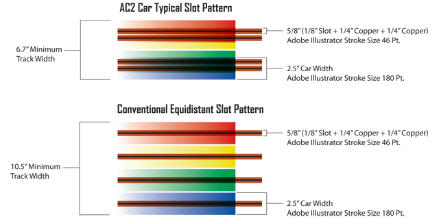
This is based on a four lane track. You can instantly see the road width advantage of AC2Car Spacing. I use Adobe Illustrator for track design, if you are familiar with it or other graphic vector programs such as Corel Draw you can do it too. I look at a track design in two distinct ways for AC2Car. One is the slot and copper spacing which I call Copper Collision Drawings. Number two is car spacing which I call Car Collision Drawings. In Vector based programs you can draw singular lines and apply stroke widths to them. Stroke widths are merely a visual width of a line, the program and others still see it as a singular no width line which is useful down the road. You can draw line segments with a pen tool in the software and apply the appropriate stroke width to it to see how things are running together. Obviously you don’t want the copper from one lane touching another and depending on the type of track you don’t want cars running into each other. In AC2 Car’s case its a little of both. You can find explanations of that in the Track Building section. In the graphic above I’ve noted Adobe Illustrator stroke values for the copper and slot width as well as a 1/32 scale car width. By combining the two visuals you can create a succesful plan before routing a single piece of wood.
Bob Asks: “How do I change the font size of the site?”
If you are using Internet Explorer
http://www.microsoft.com/enable/training/windowsvista/webtext.aspx
if you are using Firefox
View > Zoom > Zoom In or Zoom Out
Walter in Switzerland asks:
“some times ago I hade asked you about a lapcounter. Have you found a good solution for the laptimer? What type you use? Is it possible to build them byself?”
There are two solutions to this question, but in general:
YES we have a good solution and YES you can make it yourself.
Both solutions hook up to a computer and both can be made for less than $50!
- We have a timer that hooks up to the parallel port of a computer and uses the lap timing software of your choice to count the laps. This circuit came be made with parts from your local electronics store or online retailer like digikey. The schematic for this is on the Electronics page. Dan, of the amazing 1/24 scale Cactus Creek Raceway, has been using this circuit with great success for over two years now.
- Bryan is working on another more advanced hardware and software program that connects to the computer via USB. This hardware is in the final stages of development and we hope to give it a field test on April 11th.
So in both cases, you will need a computer running Windows or DOS depending on the timing software that you use. I have used both SRM and Lap Timer 2000 with great sucess. Personally, I prefer SRM because Lap Timer 2000 doesn’t take up the whole screen.
So head over to the Electronics page and scroll to the bottom of the page for the schematic!
For your lane changer, we know that you use a 12 volt solenoid and return spring connected to a bent 1/8 steel rod to guide the shoe from one lane to the other. But when you run two cars (“A” and “B”) in a lane, both run very fast and near one another. Say car “A” is first, and “B” goes through second. But, both cars run nose to tail. How do the drivers of car A or B put on the switch and not disturb the other car? How the does the switch “know” who wants to change the lane and who does not want to do it? Can the A driver send a different signal to the switch than the B driver?
First see our Lane Changing Page.
The problem of a driver holding his lane change button down too long sounds worse than it is. Yes, both A and B driver’s buttons are wired in parallel to the same switch. No fancy electronics are really needed. The decisions are totally up to the driver. If driver A wants to be kicked off my track, he can just keep holding the button down as driver B 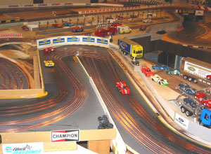 goes through the hairpin turn where the lane change switches are. There must be discipline in any form of racing. The decisions are totally up to the drivers. If they just change lanes blindly, they are going to ruin the race. Anyone model racing with two or more cars per lane must adhere to the same common sense rules that apply to all forms of racing, or be black flagged. We are not just watching toy cars zip around here! We are miniature racing. We are replicating an actual car race of a period with the finest scale models that we can build or buy. On digital race tracks the cars seem to be flying around like magnetized bumble bees stuck to the track. The track’s electronics on these sets, does the thinking for the drivers. The only time the cars look like real race cars is when they get picked up off the floor after they bash together at the switches! The secret to a good AC2Car routed track, which allows two cars to run in the same slot, is that the track needs to have it’s lane changing area designed just past a chicane, or hairpin. Just before the switches, the track necks down to force the field of cars to go through a tight roadway more slowly, and in single file. This not only minimizes shunts that occur as cars cross other lanes, but it allows the time to make a decision as to whether to stay in the regular lane or cross to the passing lane. Something that digital cannot provide. Again, holding the lane change button down as the other car goes over the lane change switch does accidentally happen, but it’s rare. The way we race, if a slower car is blocking, 1) The slow driver will let the faster car pass. No different than what is expected in real racing! 2) The faster car that needs to get by will drop back as he comes to the switch, because he not only has to negotiate the hairpin turn, or chicane slowly in single file, but he needs
 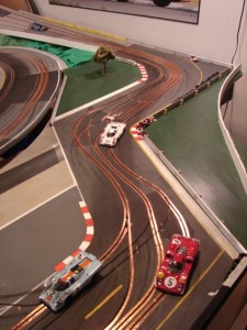 to see which side of the track the car in front decides to choose to race on. No one can pass you because the whole field of cars behind your car are forced into single file as they go through the tight hairpin or chicane. Just like real racing, a driver sees which side of the roadway the slower car chooses as it exits the turn and he takes the opposite side. This careful planning allows him the whole next lap, to beat the other car back to the lane switching area. Each time the cars slow and regroup at the hairpin, or a chicane, that decision is made again. No different than what Mario Andretti needed to do at narrow chicanes and hairpin turns on every lap, of every race, he ever ran in. If a driver on a track with two cars in one lane, does not race as the real cars do, than he deserves not to race on tracks such as these. He should go and spend triple digits on a digital set that does the thinking for him. That way he can watch cars fly around mindlessly, at least until one or two of them end up side swiped off the track.
No need to specifically use a train transformer, but we just thought it would be easiest to point guys to those. They have good adjustable voltage range and are easy to wire up and available on eBay.com for not too much money.
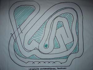
How do the marshals get inside the track to put the cars back on the Legends Track?
Unlike my Northline Raceway, right from the start we designed Dave’s Legends track to be set up to use 2 foot gripper tools. I began using them for the kids to use when marshaling at my track. Grippers are 24 inch long wands with hand controlled clamping abilities used to reach high shelves or install light bulbs in high places. They are sold under different names at hardware stores. They have rubber claws that hold a race car firmly, yet gently. We did design in an access point in the middle of Dave’s track, but it will only be used for construction purposes and may be covered with a lift off removable scenery panel. There were about 5 places on Legends that I thought would only be accessible using a Gripper, but as it turns out three of those marshaling points can be reached by most adults. By extending a marshal’s reach another 2 feet, we were able to design in far more track to race on. If had to design my track over again, I’d worry less about accessibility and add more linear feet of track into the space. The AC2Car form of racing is more disciplined than magnetic “rhythm” racing. Cars on AC2Car tracks do need marshaling, but the models are not flashing around in a blur, flying off all the time. However I have to admit, that when the kids race here we have more than out share of fetching downed cars. But, the Gripper type tools work well.


